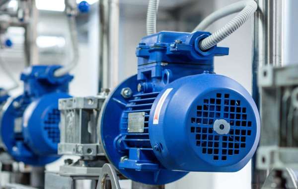
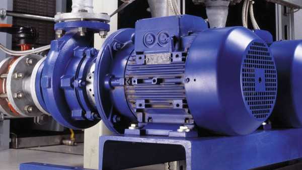
The armature of an electric motor helps transform electrical energy into mechanical energy. It typically consists of copper bars with the insulation between them, joined by ends that are connected with coils that are connected to commutator segments. A surplus motor is the greatest Motors Voltage applied to the brushes of a motor causes them to become in contact with the commutator segments. This is called an AC voltage. It increases when the motor is close or moves away from its pole.
Commutator
Commutators are a type of bar made from metal. They change the alternating current within an armature to direct current for use by motors, and guard against switching polarity. The commutator is situated between stationary brushes and the armature's core, the commutator consists of copper wire insulated with mica (though other materials can also be used).
The armoury is a coil of conductor wrapped with wire that produces magnetic fields with an angle to the generator's field, resulting in shaft torque (rotating machine) or force (linear machine). The coil's purpose is twofold that is to conduct current while also cutting electromagnetic flux that is produced by the field coils.
An armature coil comes in two types: lap wound as well as wave wound. When a armature is lap wound every coil's final edge connects directly with its respective pole through a segment of commutator as their principal ends join directly to brush segments on each end.
The volt/ohmmeter may be used to test the resistance of an armature windings' resistance, in addition to the commutator bars' resistance. in a 180 degree space from one another.
Windings
The armature windings of an electric motor comprise copper coils that are connected to its motor's commutator. Insulated between each conductor and away from the core, these conductors can reduce eddy voltage and hysteresis reductions. They could be lap wound or be wound in waves based upon the amount of current paths and voltage levels are desired.
The armature's core usually consists of several thin plates of metal called laminations with thicknesses that range from 0.5mm and 1mm. They're then put together to form the core. After being assembled, the laminations are then pressed into a shaft form using the pressure of pressing machines, as well as slot stamping machinery using slots that are stamped on where coils will eventually rest; Additionally, this type of core comes with a coarse knurl, which aids the commutator in engaging it in a proper manner.
While current moves through the armature, electrons within its coils become freed up and create a magnetic field which is opposed to the flow of electricity as well as a magnetic force, which rotates the rotor, generating electricity.
For magnets to work properly it is essential that the armature be properly configured. It needs to be set in a straight line towards the field to allow the shaft's torque or linear force production (rotary machine) or brush brush current through stationary brushes and onto commutator bars with equal resistance readings on an ohmmeter which shows the functioning of the armature.
Slots
In a motor, slots are slots designed to increase its effectiveness by connecting coils of copper conductor to its commutator and reduce copper resistance losses, while at the same time limiting electromagnetic force that causes cogging. Armored coils are located within these slots. They connect with a two wires that are insulated to the commutator. Once activated, their magnetic fields create Lorentz forces, which push its rotating rotor in the direction of.
Commutators are metal rods used to transfer energy mechanically from motors to the loads they carry. Positioned between rotor and stator for reducing harmonic distortions and vibrations, their length and speed have to meet the demands of torque of each machine for effective operation.
An ideal armature must minimize iron losses resulted by eddycurrents - minute magnetic fields which form when two magnetic fields intersect and spin - forming in metal due to rotating magnetic fields. Eddy currents are reduced by ensuring that copper conductors within the armature are designed so they do not cause flux cuts between copper conductors inside the armature. buy electric motor from surplusrecord industrial electrical surplus motors . They're the ideal choice for electric motors. used electric motor for sale at surplusrecord.
In addition, an ideal armoury should be equipped with the right number of slots to produce an ideal magnetic field determined by dividing the number of poles with its rate of operation. An ideal armature should produce magnetic fields where the geometric neutral axis (GNA) is in line with an angular deviation from a commutator bar.
Core
The core is a strong rod, which is used to support the arms. It is fitted with slotted edges that allow rotation when activated by electricity, and insulation to stop the arcing of brushes between the brushes. Furthermore, the power of mechanical force emanating from the source is brought to it through the rotor shaft channel.
An electromagnetic field is created by a conductor that loops through the iron teeth and is connected to a commutator bar. The current produced draws permanent magnets into stators whose magnetic fields result in what's commonly referred to as Lorentz force. This force could then create torque within an electric motor.
This magnetic field could be altered by adding eddy-current losses, and also changing other elements, like winding polarity. The coils on an armature may be wound differently based upon the model of the motor as well as demands for power output. Furthermore that the bigger conductors result in greater copper loss due to frictional losses.
The core and commutator are usually separated by the use of an insulating material, like sheets of mica, or thermoset plastic, to keep copper wires in the armature to touch one another and touching each other during its rotational path. Armored armatures could be wound with wire coils. Some designs feature slots twisted in order to avoid cogging. These designs also allow for level movement from one pole to the next.